Part definition: Multiblade
Introduction
This topic will explain the options found in the Part definition tab of the Multiblade operation.
Part definition
The Part definition tab allows you to select the required geometry for the feature, define the part and any check surfaces. This tab also allows you to determine how much of the part is machined and in which direction, as well as the machining tolerance of the created toolpath.
Part Definition
Note: In the images below, all instances are highlighted. When choosing geometry for an actual operation only a single instance should be selected with two exceptions: using the Pocket option for the Contour strategy for Blade finishing, and for Roughing operations. In these instances selecting two blades, and a splitter when applicable, is necessary in order to define the area between them.
-
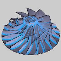
Blades, splitter, fillets - click
 to enable selection mode and select the surfaces of the blades, fillets, and splitters if splitters are present.
| Blades | Splitters | Fillets |

|

|
|
-
Stock to leave - is the amount of material that remains on the surface (for finishing).
Important: When applying the Swarf Strategy to the Blade finishing pattern, the fillet should be excluded from the select geometry.
-
Hub - click
to enable selection mode and select the hub surface(s).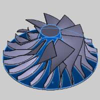
-
Stock to leave - is the amount of material that remains on the surface (for finishing).
-
-
Shroud - click
to enable selection mode and select the shroud surface(s).
-
Start offset - allows you to create an offset between the shroud and the first cut.
-
Important: When applying the Swarf Strategy to the Blade finishing pattern, it is necessary to exclude the shroud from the select geometry. Otherwise you will receive error: Exception raised in calculation routine ( Could not generate swarf milling tool path. Please verify the input data.)
- Check surfaces
 - No additional surfaces will be checked.
 - Allows you to select additional surfaces to apply a specific clearance value to.
Clearance - specifies the clearance amount use on the selected surface(s).
-
Rotation axis - The rotation axis of the part must be defined using either:
-
Automatic - allows the system to detect the rotation axis to utilize.
-
User defined - allows you to select a specific rotation axis and a Rotation axis base point.
-
-
Rotation axis base point - click to launch the Rotation base point dialog. This allows you to define the distance from the Machine Setup (machining origin) to the rotary axis of the part. If the Machine setup is aligned with the rotary axis of the part, the Base Point values should be X0Y0Z0 (for most scenarios). As another example, if you set the Machine Setup to the top of a four-inch cylinder, you define the Base Point as X0Y0Z-2.
-
Number of segments - allows you to enter the total number of blades on the impeller so the path can be patterned appropriately.
Segments
-
Machine - These options dictate whether all segments, which are defined in the part definition, or only a specified number are machined by this operation. The three available options are:
-
All - machines all blades as defined in the part definition.

-
Determined number - allows you to specify a certain number of segments to machine.
-
Determined by geometry - machines only the geometry selected in the part definition.
-
-
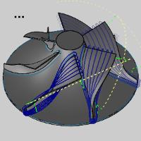
Start angle - The start angle defines the start angle of the toolpath according to its initial position. The start angle for the segments can be set as:
-
At segment - begins at the current segment and the angle to the next is calculated automatically.

-
User defined - allows you to specify an angle from the currently selected geometry to begin the toolpath. Selecting 180 would cut the geometry on the opposite side of the part.
-
-
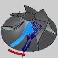
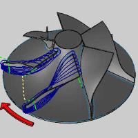
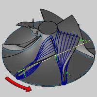
Direction - The direction determines whether the rotation sequence goes clockwise or counterclockwise.
-
Clockwise - moves the cuts in a clockwise direction around the part.
-
Counterclockwise - moves the cuts in a counterclockwise direction around the part.
-
Quality
-
Machining Tolerance - type a value to define how accurate the toolpath is in relation to the selected geometry. Smaller values create a more accurate toolpath but also increase calculation times.
Tip: You can reduce the cut tolerance value, for example from 0.0005 to 0.005, to speed up the toolpath calculation while creating and modifying your toolpath. Once you are happy with the result, you can then set it back to the original tolerance to calculate the toolpath before posting the output.
- Maximum distance
- Select the check box to use the value specified as the maximum distance between toolpath points. - Clear the check box to turn off this option.